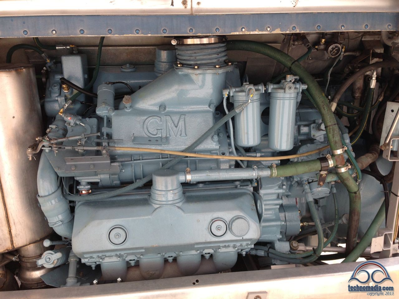
 It took longer than any of us imagined it might.
When we broke down on June 14th, the thought that we might still be in Billings when Cherie’s 40th birthday rolled around on August 4th seemed like something to joke about.
That was over a month off!
Even considering the time it took us to come up with a plan of action, the initial estimates we received from Interstate PowerSystems called for us to be back on the road no later than mid-July.
But it turns out – major repairs on machinery older than we are is nothing to joke about!
Things seem to have a way of taking longer then you might have imagined, especially with an engine as “special” as ours.
First we spent some time settling on a plan.
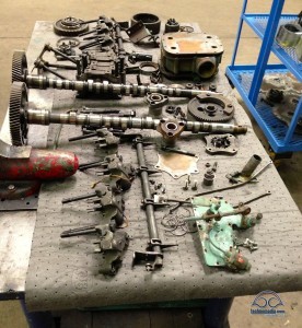
Then we disassembled and dissected the engine down to its base components.
Old parts were cleaned and inspected. Replacement and rebuilt parts started to arrive.
Video Summary
What follows is a very long post overviewing the rebuild. We’re amazed at how much we learned about the operations of a 2-stroke diesel engine – and we’ve become fascinated with this stuff.
To summarize the rebuild process, we also created a quick video montage that brings it all together in under 5 minutes that you might enjoy as a supplement to this post… or as a visual recap if the details are beyond your interest level. (direct link)
And then, the week of July 8th, we started to rebuild…
If we had only known we’d still be in Billings 6 weeks later…
Though our engine heads showed no signs of being cracked or having suffered damage – without a microscopic inspection it is impossible to know for sure. Rather than spend the time and expense to fully tear them down, inspect, and rebuild them we decided it made sense to just send them off to Detroit Diesel to be be replaced with previously rebuilt Reliabilt heads.
We got lucky in this process – the heads we received were actually brand new, not rebuilds!
It seems that there is a shortage of old heads to rebuild, and occasionally new heads get mixed in to keep up with supply. Score!
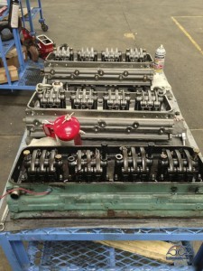 A tech was assigned to configure the shiny new heads to match the old, handling the transfer of all the appropriate fittings. It was cool to see the new heads next to the old on the bench.
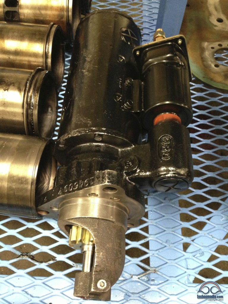
Since the engine was apart – it made sense to send the starter and alternator off for refurbishment. The starter was particularly prudent to take care of now – on a 4106 engine configuration, the starter is exceptionally hard to access and remove while the engine is installed.
Though it had been working fine, being proactive now could save us a lot of future headaches down the road.
Here is the newly rebuilt alternator, which the shop reported was performing “underpowered” and needed a bunch of work:
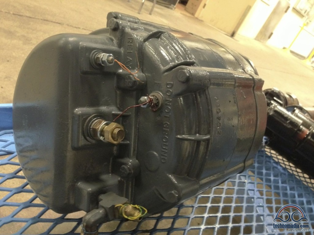
The rebuild shop reported that the starter however was in great shape, but they cleaned and overhauled it just to be safe:
The Crank & The Block
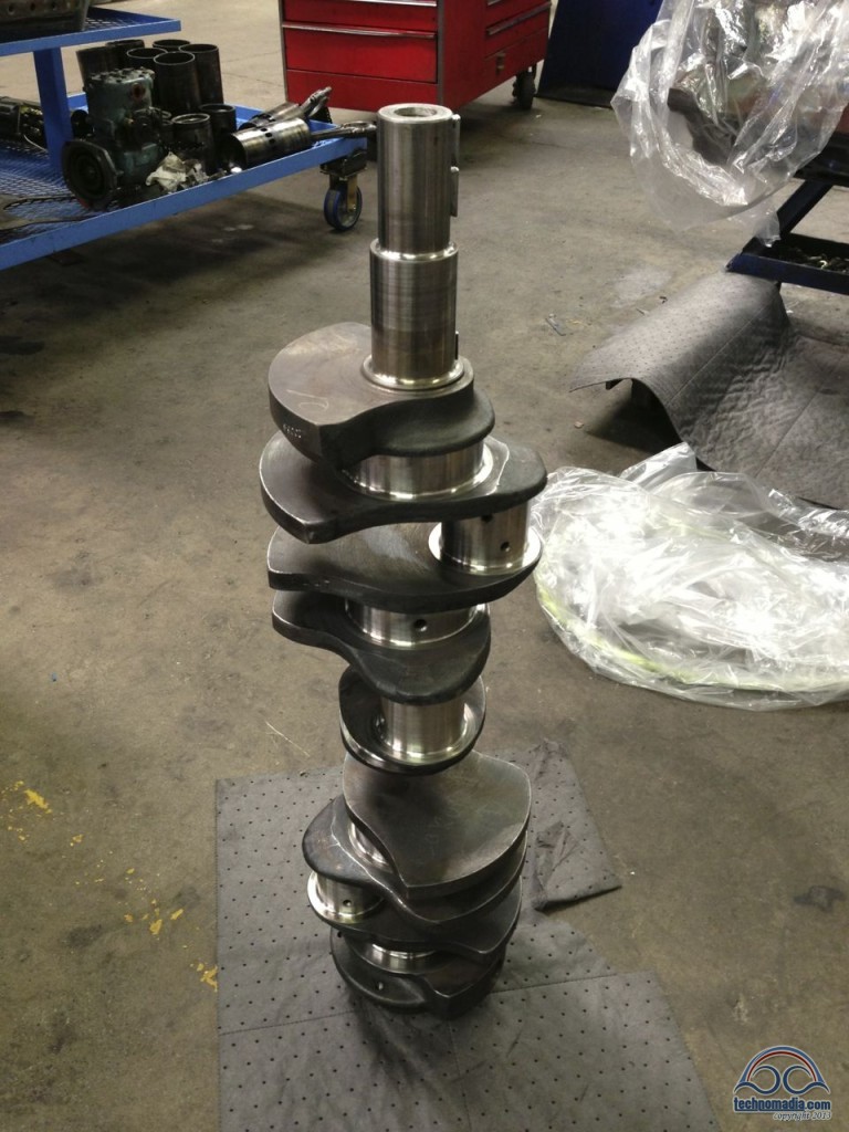
The crank shaft was sent off to a machine shop to magnafluxed and polished. It came back looking great.
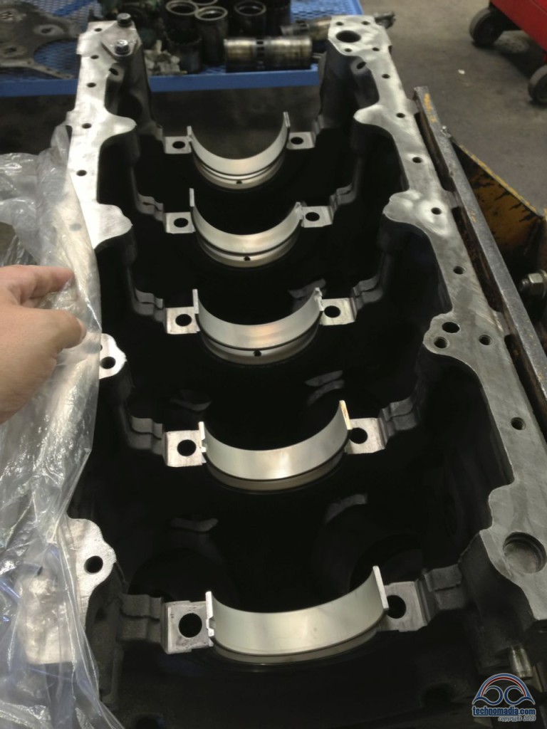
New bearings installed into the block to support the crankshaft:
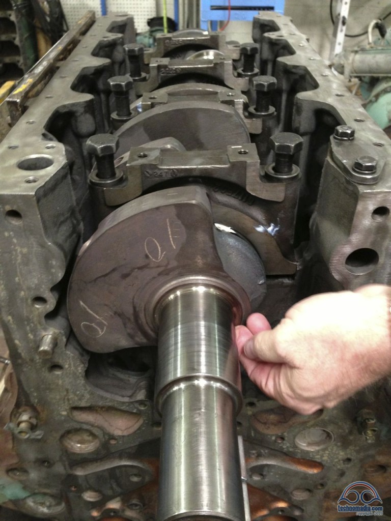
And the crank shaft was then re-installed in the bottom of the block:
Pistons, Rods, and Cylinder
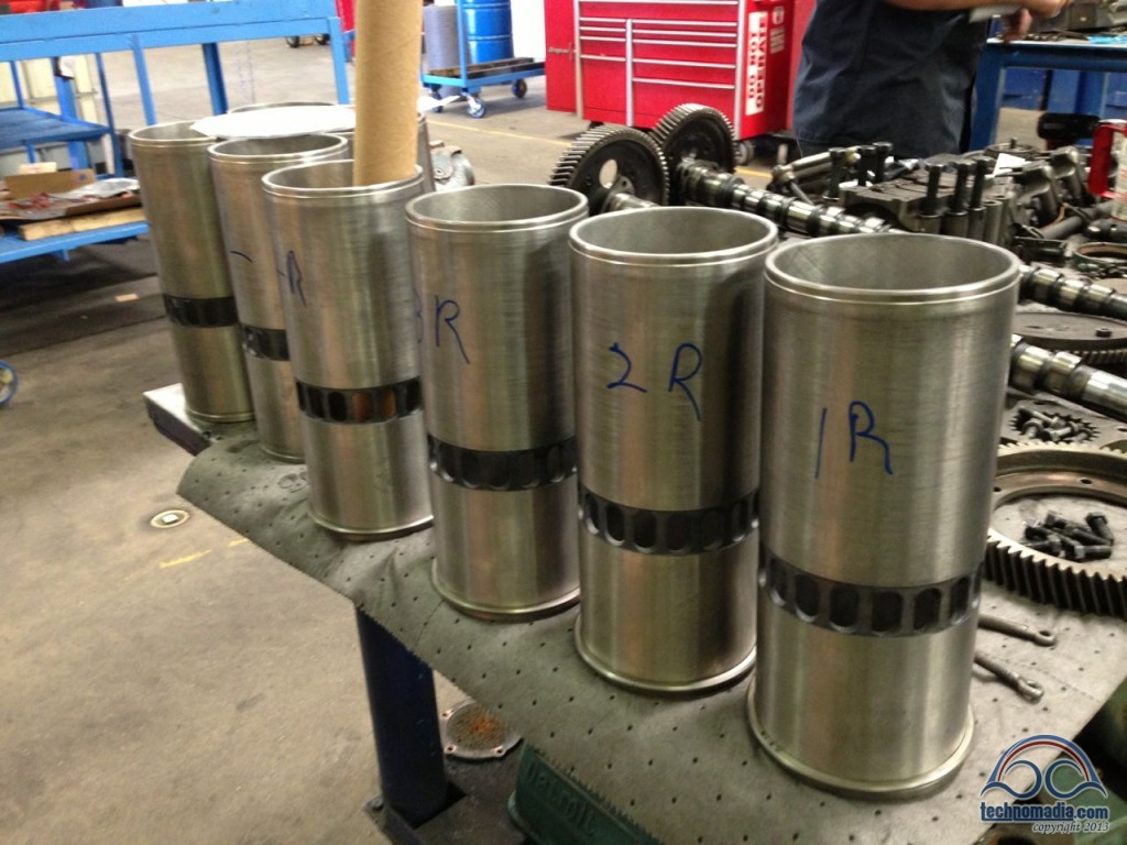
The new cylinder liners were sized and fitted to their best matching bores in the block.The holes in the side allow air to enter the cylinder before being compressed by the piston on the upstroke:
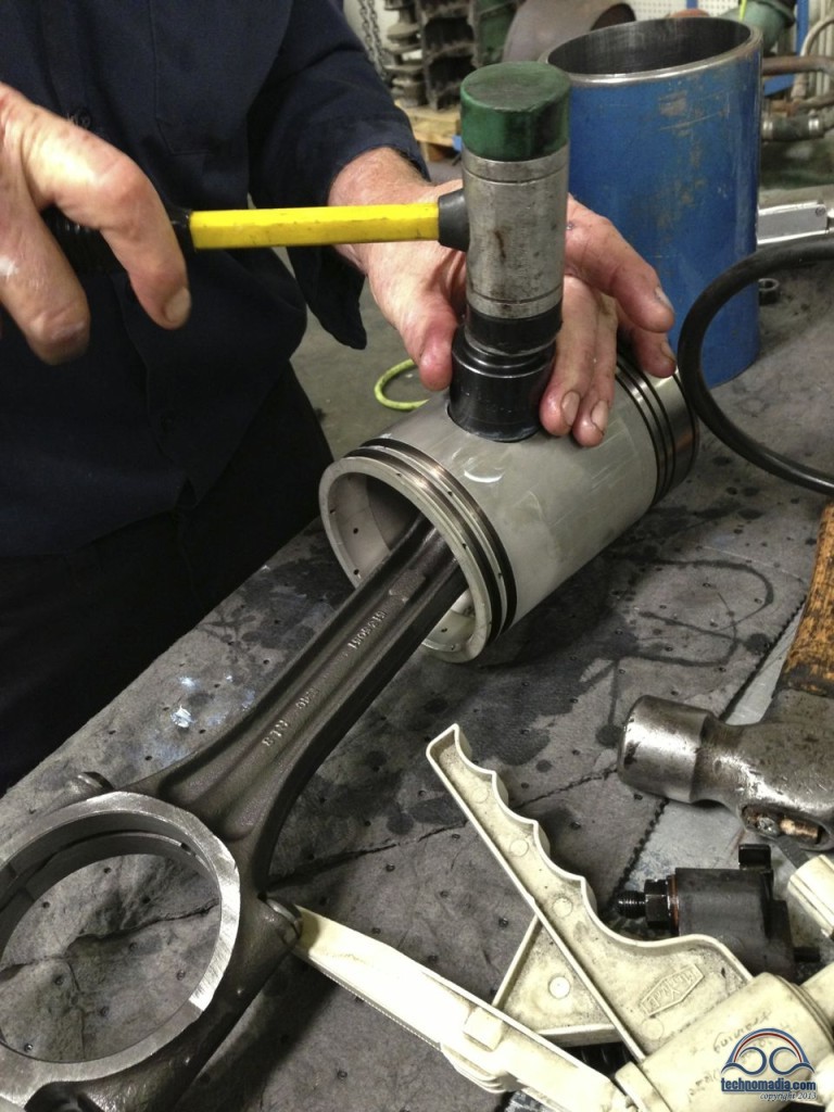
Rebuilt connecting rods were mated with the new pistons:
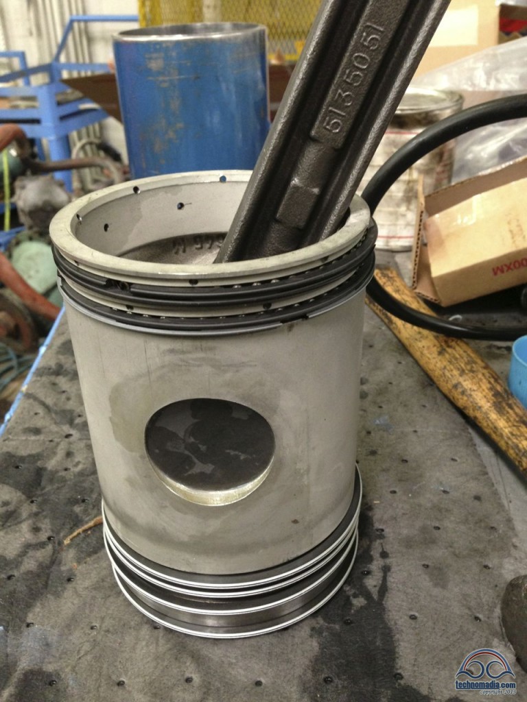
And then the piston rings were carefully fitted – these are metal “bracelets” that form a seal between the edges of the moving piston and the cylinder walls:
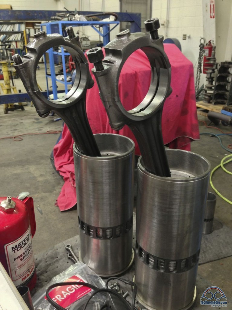
The entire assembly was then carefully mated with the cylinder liners (watch the video above to see how it is done):
Next the engine was rotated so that the cylinders sleeves and pistons could be inserted, and the rods attached to the crankshaft. Like an eight-legged caterpillar pedaling a bicycle, the power of the pistons pushing downward spins the crankshaft, turning the gears of the engine.
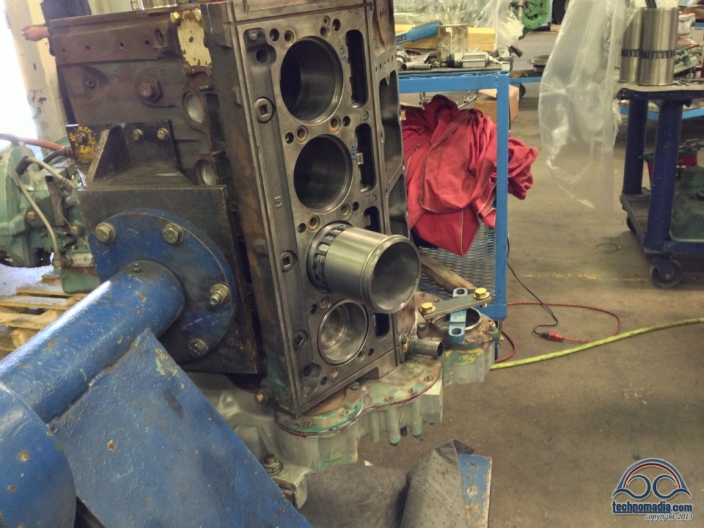
Cam Shafts & Timing Gears
Next the cam shafts needed to be inserted. These are long shafts running under each of the two heads with lobes on them that mechanically control the exhaust valves and the injectors – keeping everything in sync across the engine.
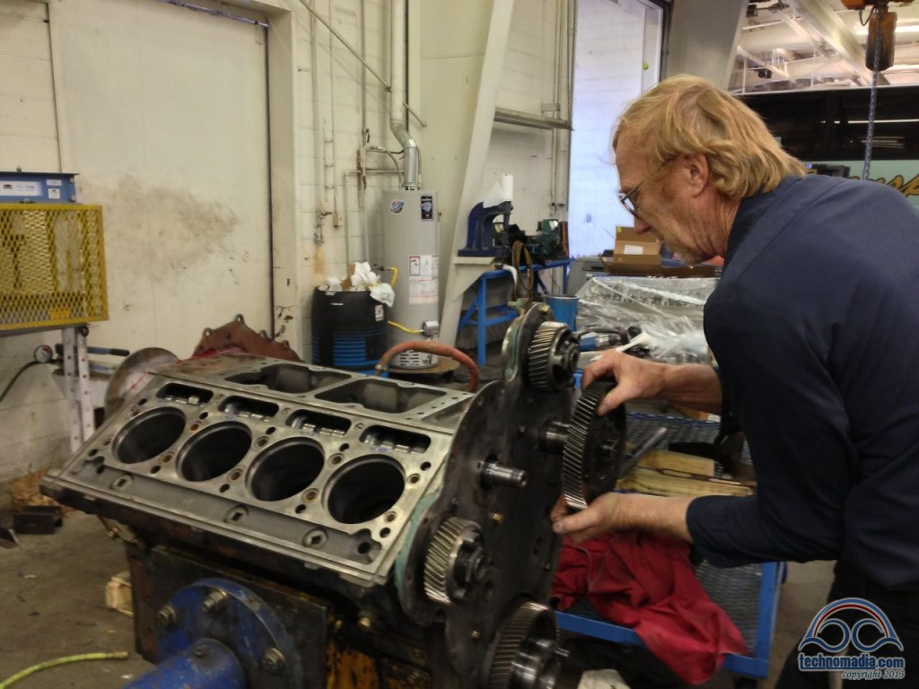
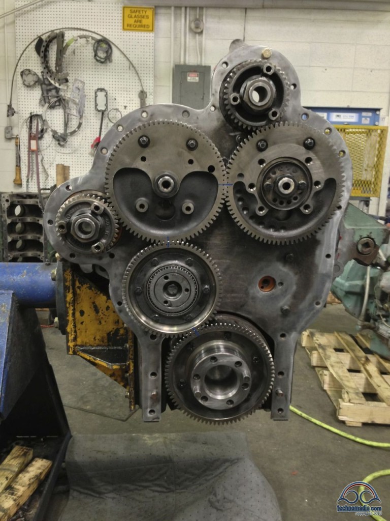
The final assembly is a thing of beauty. The gear on the crankshaft (bottom) spins an “idler gear” which is installed on the left for “left-hand rotation” engines like ours, and on the right for an 8V-71 that does not need to spin backwards.
The idler gear then spins the two big central gears which drive the two camshafts, which mechanically control the exhaust valves and fuel injectors. The top gear spins the blower, all the gears are also able to directly power accessories such as the alternator, air compressor, and power steering pump.
Everything moves in perfect sync, like clockwork.
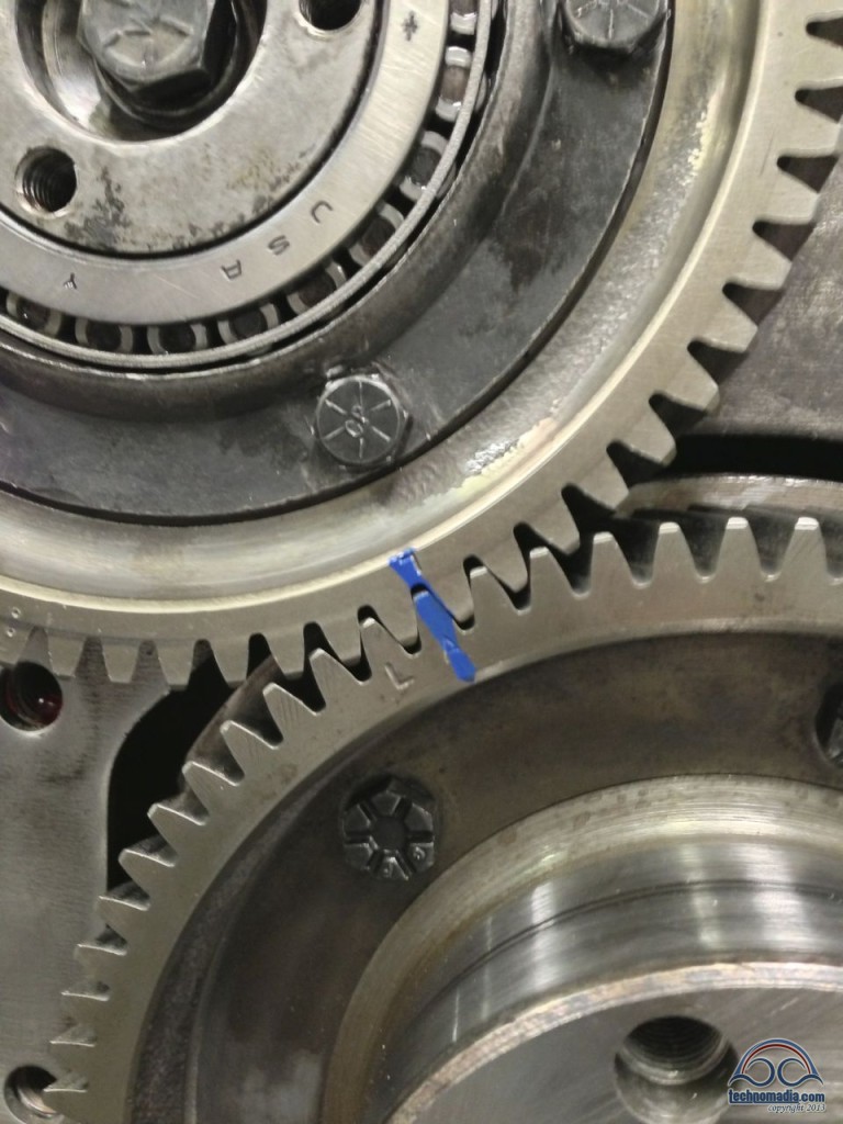
The gears all then needed to be precisely aligned for “A-Timing” which is what our engine / injector configuration called for. If you are off by even one tooth, the engine will not run properly.
The other side of the block was beginning to look like a face, the tongue being the end of the crank shaft that drives the oil pump and engine fan. The left camshaft drives the coolant pump. And the right spins a pulley that could drive a belt, but which is unused on our engine.
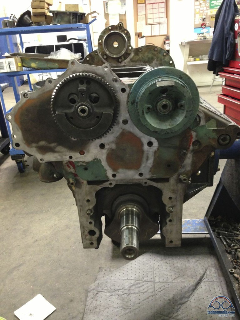
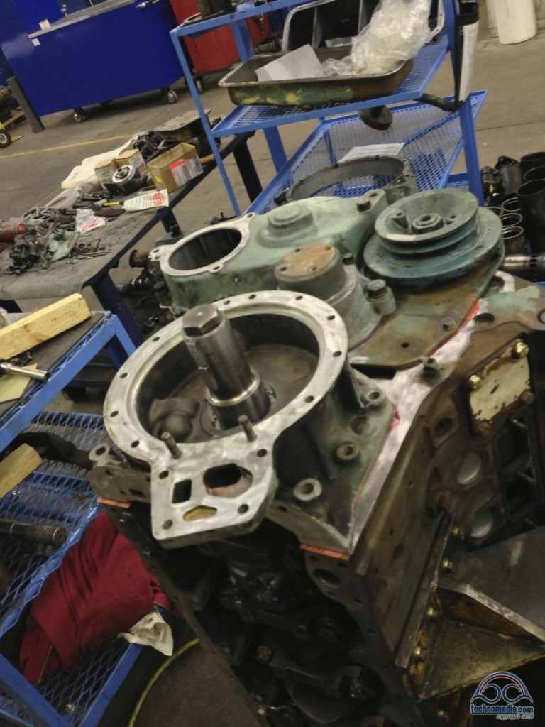
The next step was attaching the flywheel housing, which covers over the clockwork gears and provides a space for the heavy flywheel to spin. The momentum of the flywheel spinning smoothes out the thrusts of the 8 cylinders firing, and keeps everything rotating smoothly.
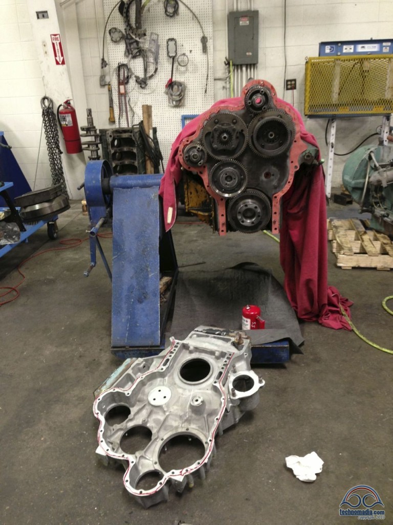
The openings are for the gear-driven accessories. From the left across the middle, on our engine the first slot is blank, then the air compressor, and then the alternator mount. The power steering pump and the blower attaches to the top gear. The starter connects directly to the flywheel through the opening on the right.
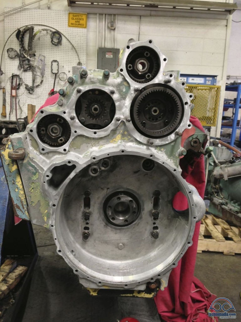
Later on, the flywheel is attached here. The provides a lot of spinning momentum, as well as mates with the transmission:
Back to the far side of the engine, the oil pump has now been installed directly onto the crank shaft. The hump in the middle is for the engine support, the top left is ready for the coolant pump to be mated, and the top right is the unused pulley.
Getting Heads
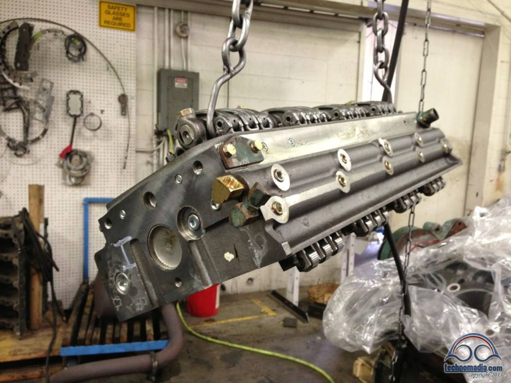
Next up, the heads were lowered by a hoist on to the top of the block.
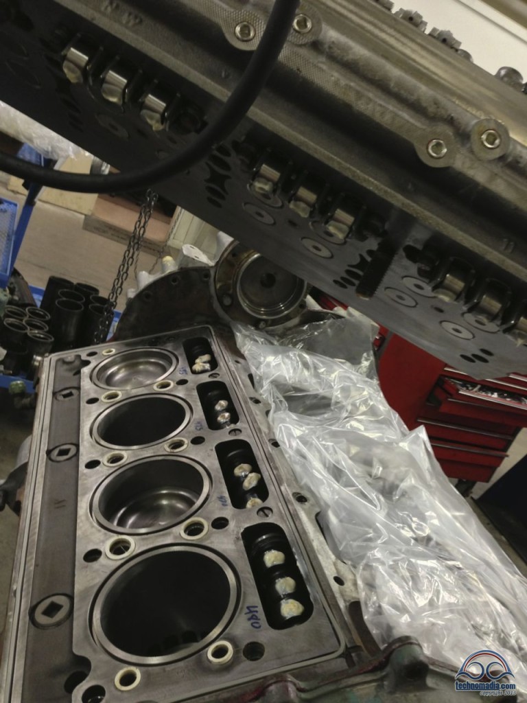
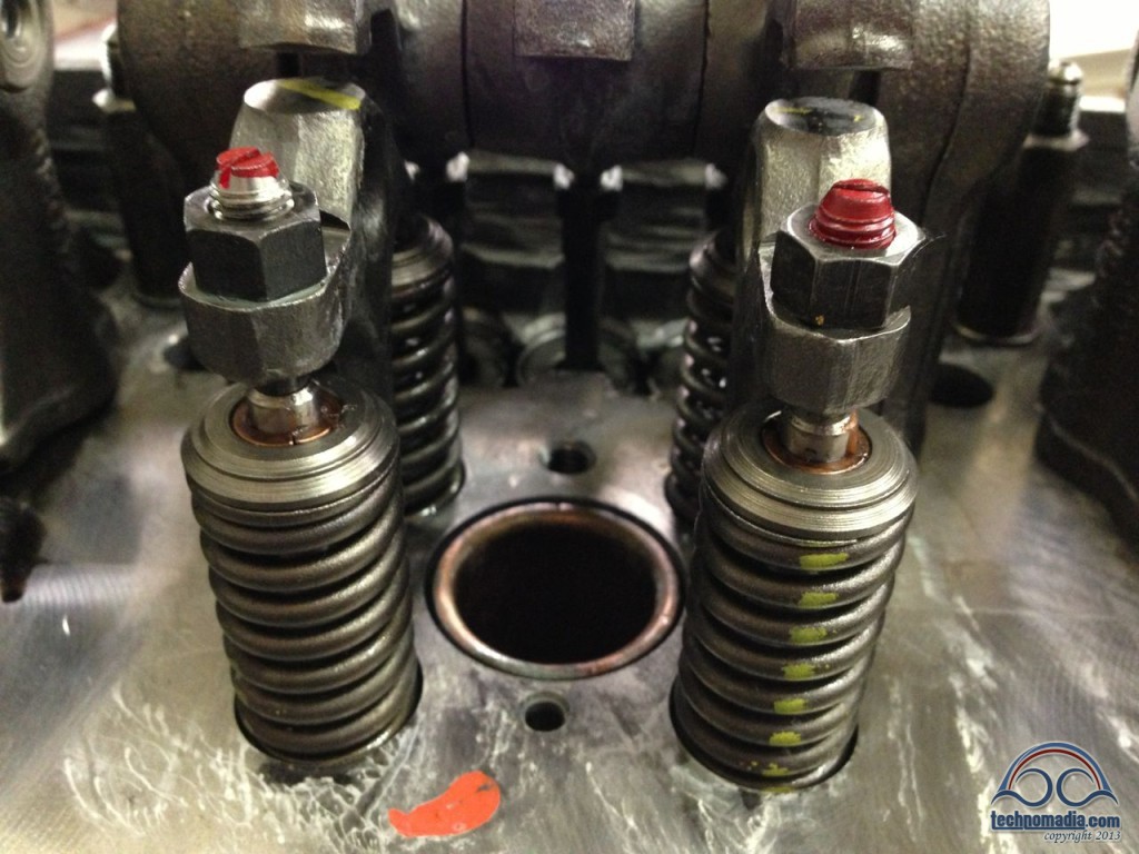
The heads are perhaps the most intricate part of the engine – you can see here the four exhaust valves (which all open simultaneously) and the hole in the middle for the fuel injector to spray fuel into the cylinder.
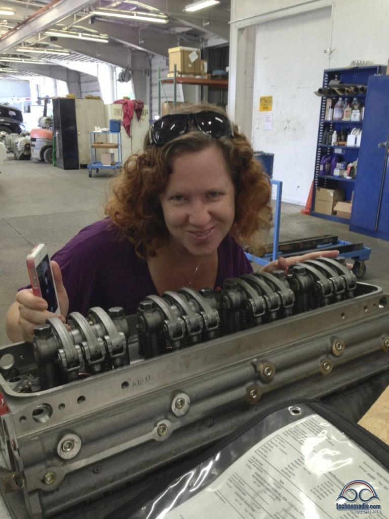
As this is a diesel engine, there is no spark – ignition is brought about by pressure as the piston compresses the air and fuel. The camshaft lobes push up on the cam followers (both covered with white lube in the photos), which act as levers to open and close the exhaust valves and trigger the fuel injector.
All mechanical magic – no fancy electronics here!
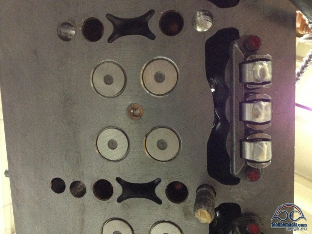
One head at a time is mated with the block, and then torqued down:
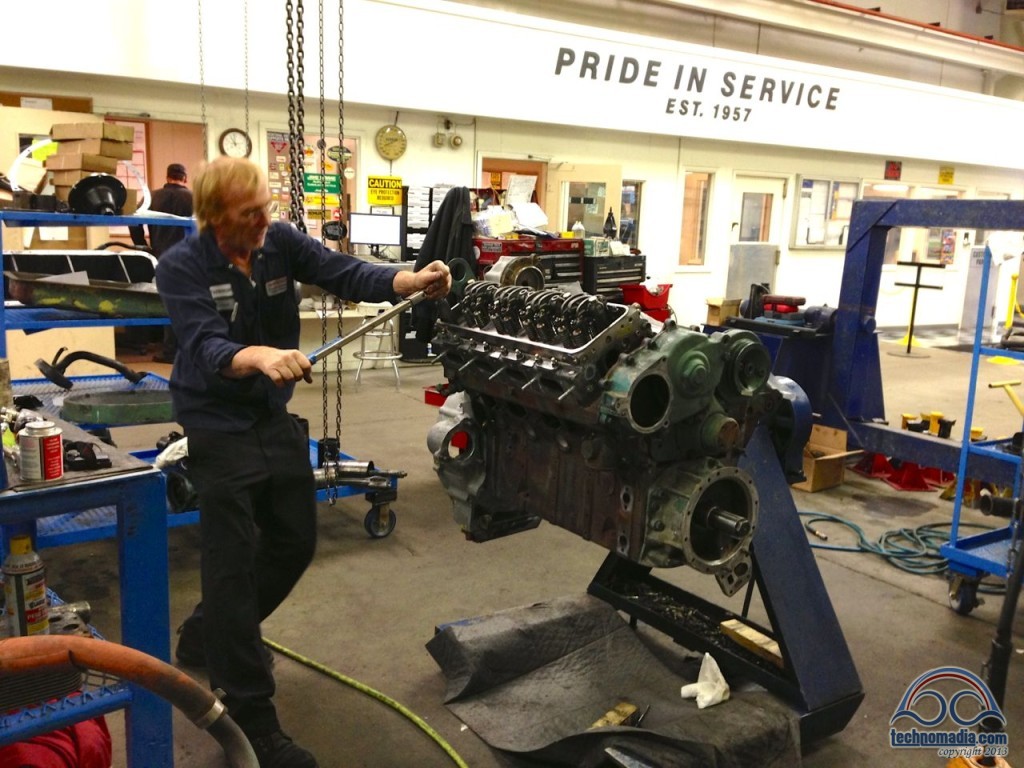
On top of each head, you can see that when the cam followers push up, the motion pushes these hammers down to open the exhaust valves. After the cam lobe rotates away, the big springs push them closed again. It all must be precisely adjusted for the engine to run right, especially at 2000rpm, and the engineering involved is a thing of beauty.
One other thing to note as the head moves into position – along the back side of the head, you can see the two integral fuel lines, a supply line which provides fuel to each injector, and the return line which sends unneeded fuel back to the tank.
In a diesel, the vast bulk of the fuel that flows into the engine actually gets sent back to the tank – helping provide engine cooling in the process.
The Cooling System
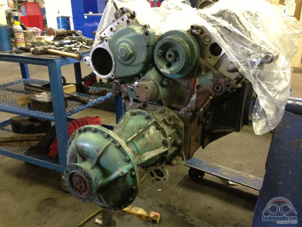
Next the large fan assembly is attached to the end of the crankshaft, sitting on top of the oil pump.
The fan is powered by an oil-filled torus that only spins when a thermostat indicates the engine needs cooling – an ingenious design that avoids wasting horsepower spinning full-speed all the time. In the original bus configuration an auxiliary drive shaft branched off behind the fan to drive the big 4106 air conditioning compressor, but that has been long ago removed in our bus.
Above the fan, the brand new coolant pump (silver) is mounted, powered directly by one of the camshafts.
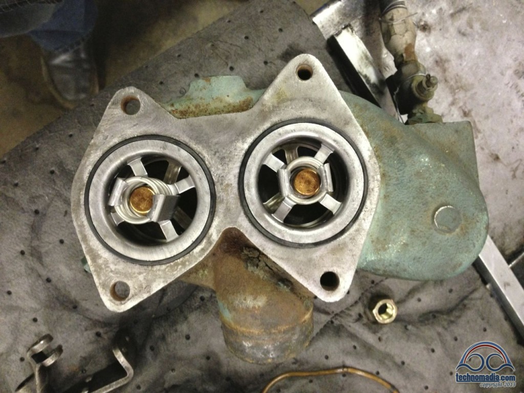
Above the coolant pump sits the thermostat housing. While the engine is cool, the thermostats bypass the radiator keeping the coolant circulating within the engine until the heat builds up. Once the engine is warm, the thermostats divert the coolant through the radiator to maintain a set target temperature. On our engine, the target is 180 degrees.
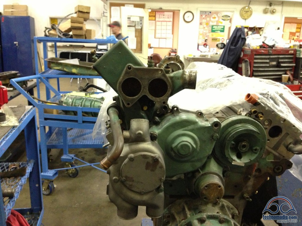
The engine has two thermostats, one for the coolant flowing back from each head. No fancy electronics here – they are simple brass pistons filled with wax that expand as they get hot. The springs squeeze them back shut as they cool.
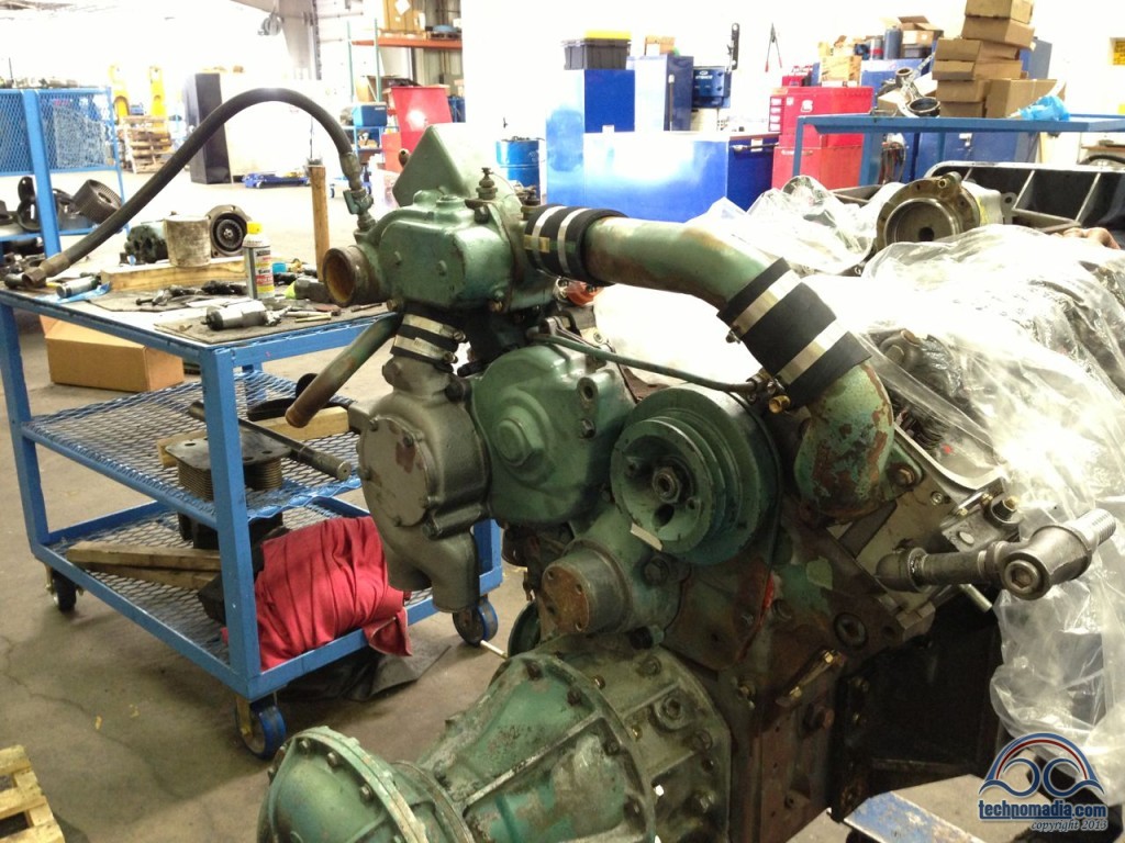
Here is the cooling system fully assembled. The coolant flows in to the pump from either above (if the thermostats are cool) or below left (which is the output of the radiator). The pump outputs lower right, which goes to the oil cooler (not yet mounted), and then flows through the inside of the block and through the heads.
The big green pipe is the output from the right head to the thermostats, the left head outputs directly in to the back of the thermostat house. And from the thermostats, the coolant flows either into the radiator or directly back to the pump.
The silver pipe on the middle right diverts some coolant towards the automatic transmission, and the copper pipe on the middle left is to the heater core for the defroster way up front. The hose dangling to the left hooks to the radiator surge tank, for filling the engine with coolant.
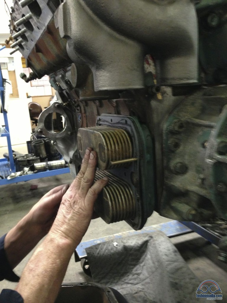
The oil cooler sits on the back of the engine. Oil is pumped through the inner coils, and coolant surrounds them.The cover that encloses the flowing coolant has yet to be installed in this picture:
The Blower
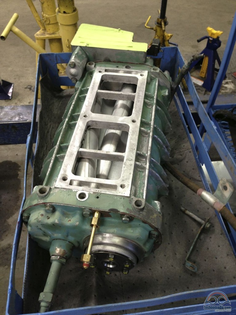
On top of the engine sits the blower, sucking in air to push through the engine.
Unlike a traditional turbo that is spun by the speed of the exhaust, the blower in a Detroit Diesel is gear driven and always engaged – pushing fresh air into the cylinders through the vent holes in the side, and simultaneously exhaust gasses out the valves in the head. In a two-stroke engine, there is no separate intake and exhaust phase – the forced air blower does all the work and the engine will not function without it.
To get it into top shape our blower was fully disassembled and rebuilt.
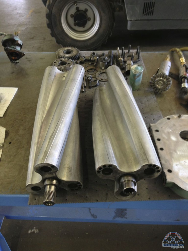
Here it is reassembled. Covered in protective tape at the far end of the blower sits the governor, the “brains” of the engine:
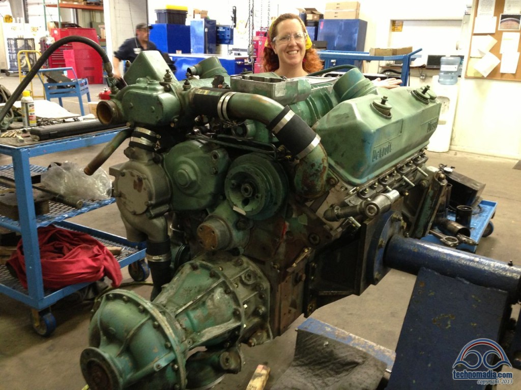
With the blower on top and the valve covers temporarily sitting in place, this is starting to look like an engine again! The cute redhead attachment is an optional feature now offered by Detroit Diesel:
Injectors, Jakes, and The Rack
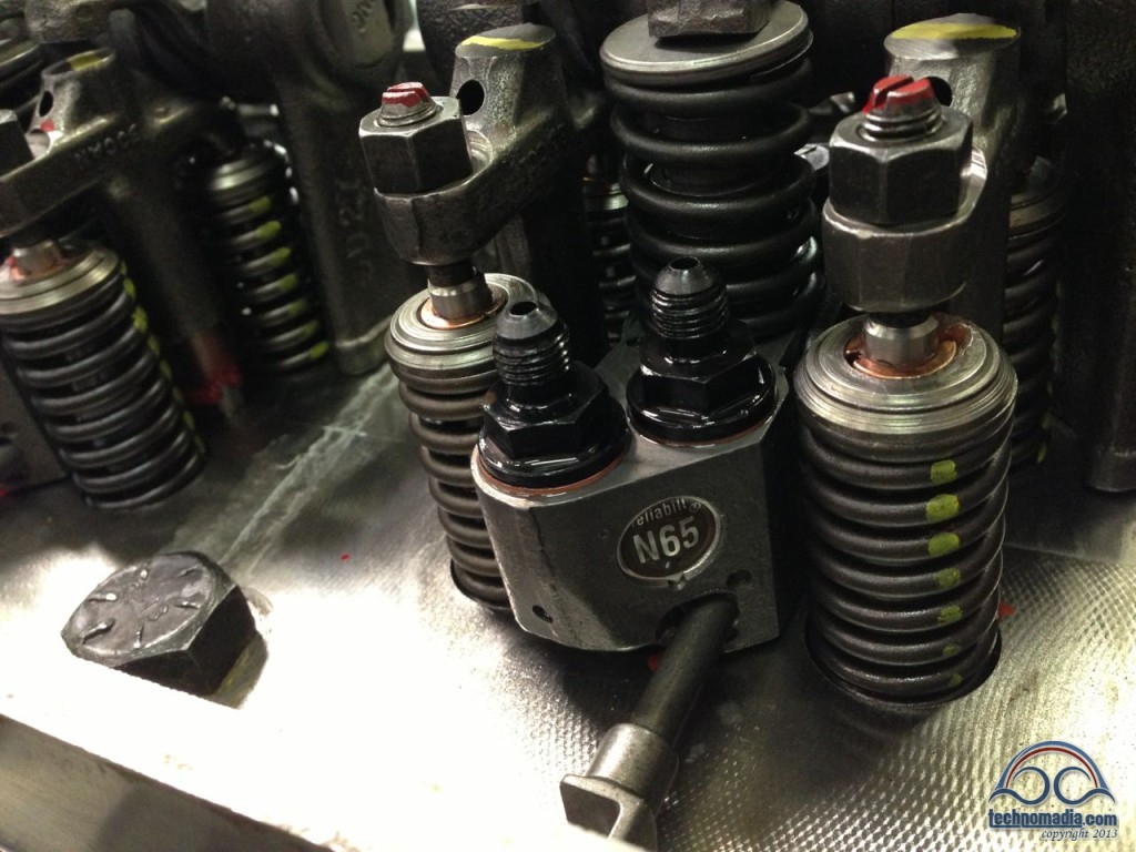
Next, the eight new injectors were installed.
After consulting with our vast brain trust of fellow bus nuts, we decided to go with N65 injectors for the best balance of power, clean exhaust, fuel efficiency, and heat generation. The little plunger going up into the bottom of the injector controls how much fuel is squirted per “pop” each turn of the camshaft when the hammer presses down from above.
The two fittings on top are for fuel lines – in and out.
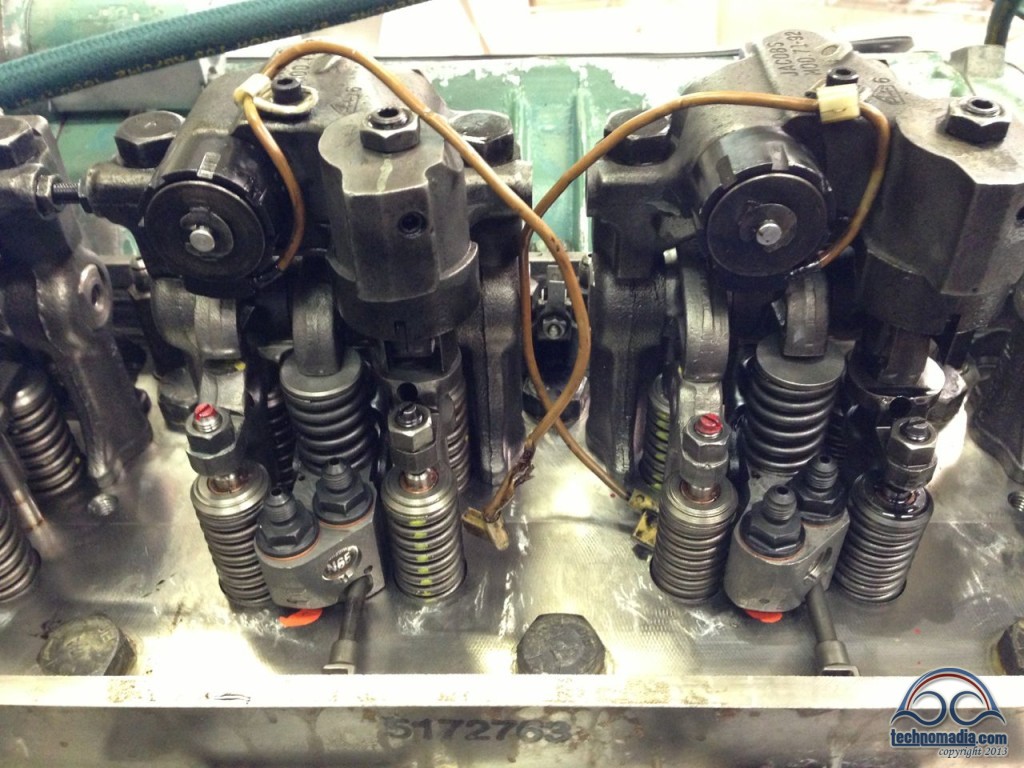
On top of the injectors sit the “Jakes” the engine brakes that when enabled release compression in the cylinders by changing the timing of the exhaust valves, allowing the engine to slow down the bus instead of relying on the conventional wheel brakes.
This makes descending a steep hill a much less stressful task, and I can hardly imagine driving in the mountains without our buddy Jake along for the ride. The 4106 did not initially come with Jakes – making space for them requires a slight bump added to rear engine hatch. Some bus nuts do fine without Jakes, but we consider it a must have upgrade!
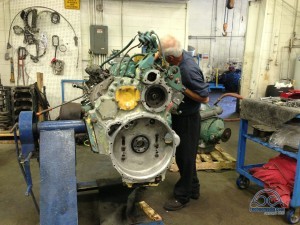 The plungers on the injectors are controlled by a mechanical “rack” that pushes them all simultaneously. A critical step of tuning up an 8V71 involves “running the rack”, balancing the rack levers to be precisely adjusted.
It is inarguably an art form to do this well, and it requires hours of intense concentration to complete. We kept our distance while the resident expert at Interstate worked his magic.
The rack on each head is controlled by rods coming down from the governor. You can see one of them at the far end of this rack view:
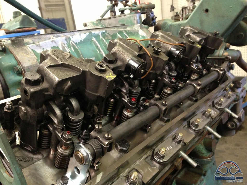
The governor is a purely mechanical brain that takes input from the the throttle cable, and works out how much fuel the engine currently needs to meet the demand.
It uses “mechanical rotating weights” tied to a shaft driven by the blower to determine engine RPM, and springs and adjustment nuts to regulate idling speed and maximum engine speed. In a modern engine, this is all computer controlled.
How the engineers in the 1930’s worked this out boggles my mind!
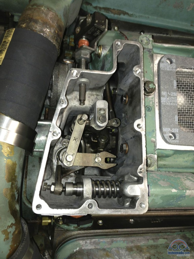
Finally – with the rack ready to go, the fuel jumpers were connected to injectors, connecting each injector up to the fuel lines running through the head:
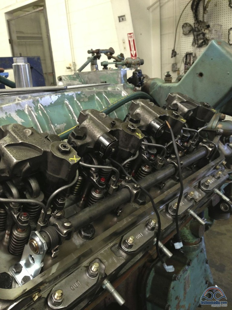
Next the fuel pump and fuel filters are plumbed in, completing the fuel system. The fuel pump is a relatively tiny component, attached to the back of the blower and tucked away down under the governor.
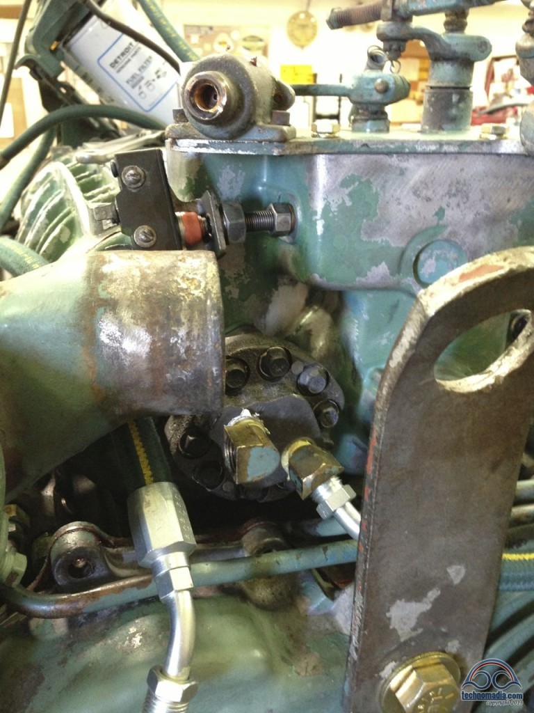
The buffer screw coming out of the back of the governor (above the fuel pump) interfaces with the Jake brakes, only engaging them when the throttle is not depressed:
The Trip to the Dynamometer
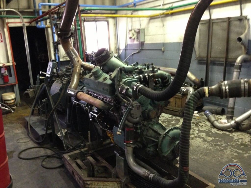
With the engine nearly ready, it was time to prepare for tuning it up and breaking it in on the dynamometer (aka dyno) – a piece of test equipment that allows for the engine to be run in a controlled environment, and its power output measured.
It is much better to track down leaks and make final tweaks while the engine is still on a test stand, and not after it is back in the cramped rear of a bus. Getting our engine on the dyno though was not without its challenges however.
For one, our engine spins “backwards” – and this dyno had never been run that way and it took some head-scratching to work out the potential issues.
Another “special” trait of the 8V-71’s used in GM buses is that they are “lazy 8’s” – they sit tilted somewhat over on their side in the engine bay. To run on the dynamometer, we needed to find a traditional non-tilted 8V71 oil pan.
Fortunately a donor was found out in the boneyard. Here is a great view of the oil intake screen being installed before the oil pan is attached:
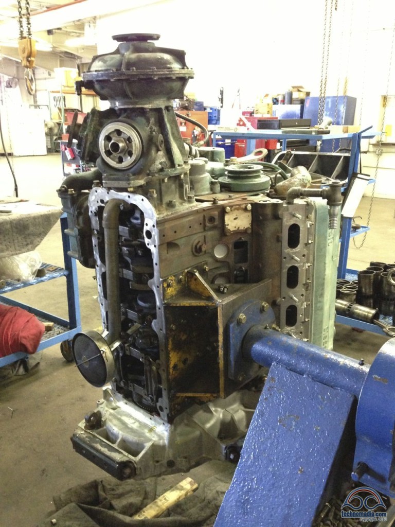
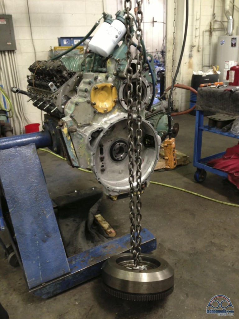
The heavy flywheel was attached, and random plates and patches (including cardboard and duct tape!) were used to temporarily cover over the accessory attachment points. One final challenge came up when we discovered that we’d need to fabricate a custom plate to mount our unusual engine to the dyno cart – but the shop dug up some metal and persevered.
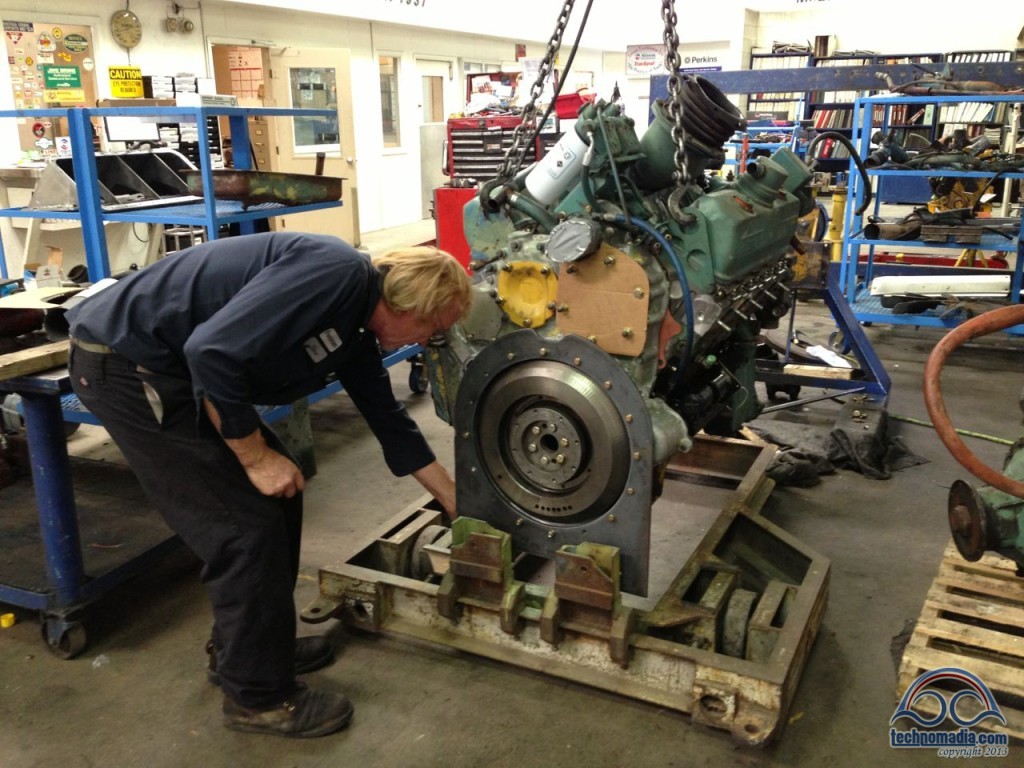
July 24th – Dyno Day – Try #1
It was July 24th by the time our engine was finally hooked up in the dyno room, and things as seemingly as simple as connecting the engine fuel lines to the dyno fuel supply turned into long delays as we waited impatiently for the right fittings to be tracked down for our “special” engine.
We were all bouncing with excitement waiting for all the pieces to finally come together – and it was a thrill to see the engine just waiting to go.
And then late in the day when the time finally came to engage…
Nothing.
The electric starter wouldn’t turn the engine over, and because our engine spins backwards the air pressure starter on the dyno couldn’t be used as an alternative means to spin the engine either.
They sent the starter back to the rebuild place to be looked over, and we all went home disappointed.
July 25th – Dyno Day – Vroom Vroom!
The next morning the starter came back as “nothing wrong with it”, and some more digging turned up something as simple as a bad end on the cable on the jump start cart limiting our starting current!
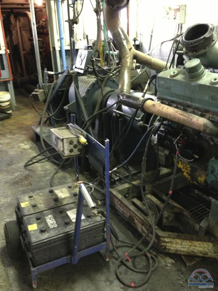
An easy fix, and then…
The engine was running great – and Larry and Steve got to work adjusting the engine idle and redline, and tweaking everything for maximum power. After all the adjustments were made and the engine had been tested out under a range of simulated loads, the engine was then “broken in” by running it under maximum load for over an hour.
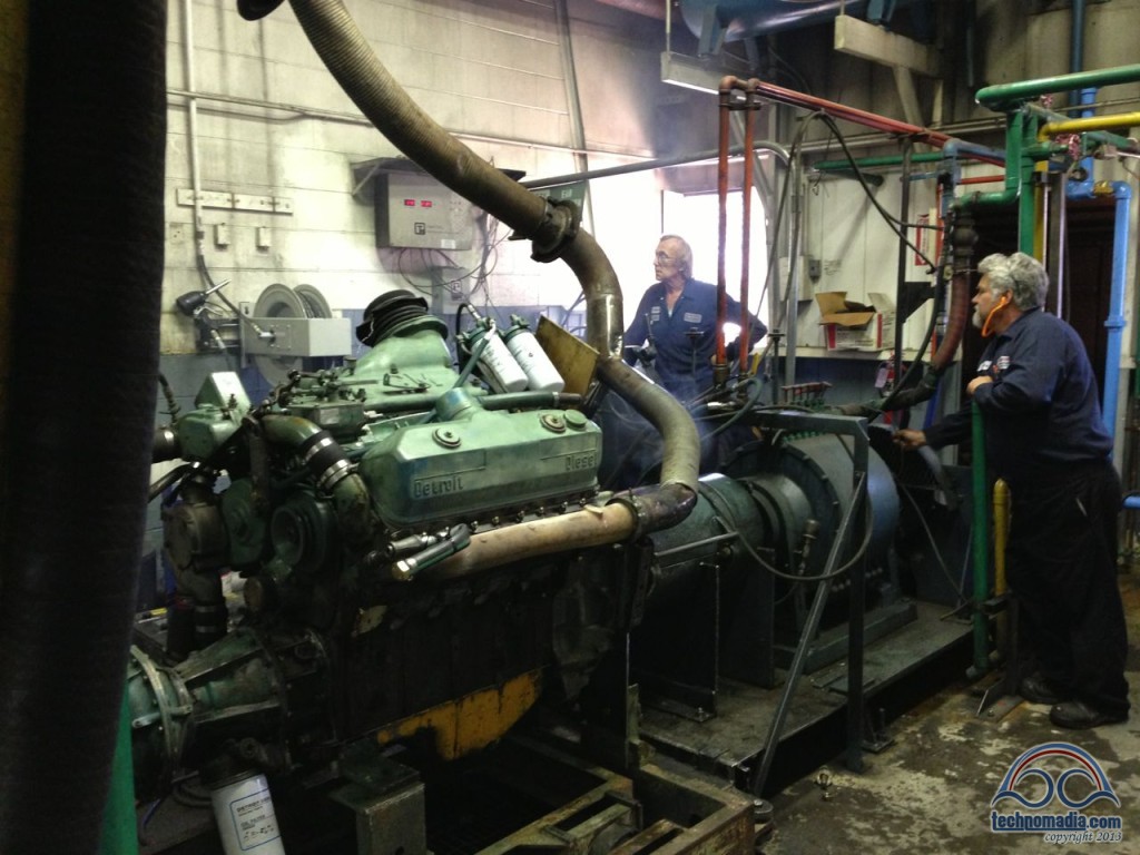
We had been expecting to see some smoke out the dyno room chimney, but our engine was running so clean that we saw none at all!
Painting, Cradling, and Mating
Now it was time to paint the engine and transmission, and to get all the accessories mounted back on. While the engine was being worked on, we had sent the cradle off to be powder-coated at ICS Powder Coating, and they had done a beautiful job – finding and fixing a few potential future issues in the process.
The Interstate crew worked over the weekend to attach all the engine accessories (the alternator, air compressor, and power steering pump), so that they could get the painting handled and give it time to dry before Monday. When we checked in on Monday morning we saw this beautiful site:
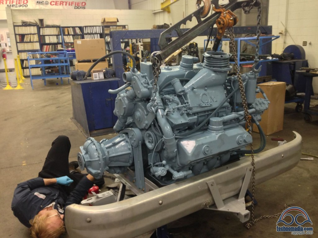
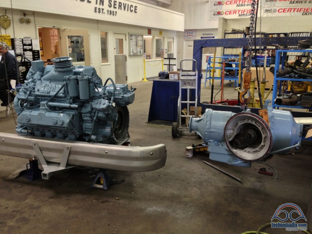
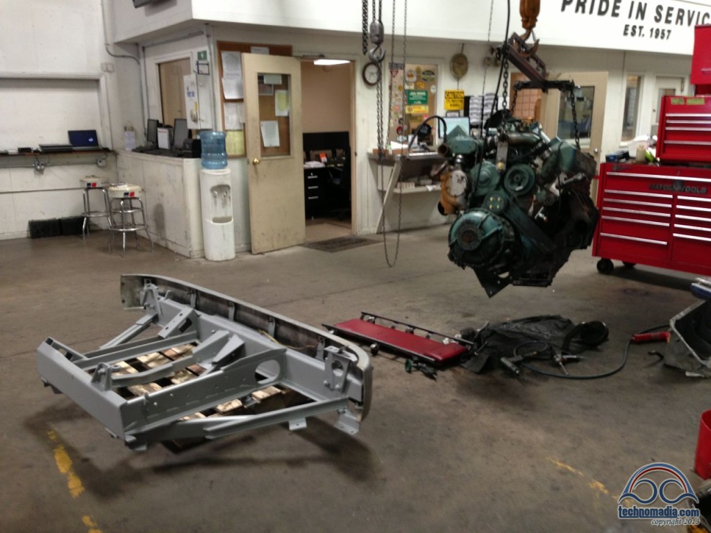
With the engine mounted snug in the cradle, the transmission was then flown over to be attached:
In this rare rear view of a 4106’s engine, you can see just how inaccessible the starter motor is – nestled on the back of the engine underneath the exhaust manifold, above the filter assembly that lets air into the oil pan, and to the left of the oil cooler:
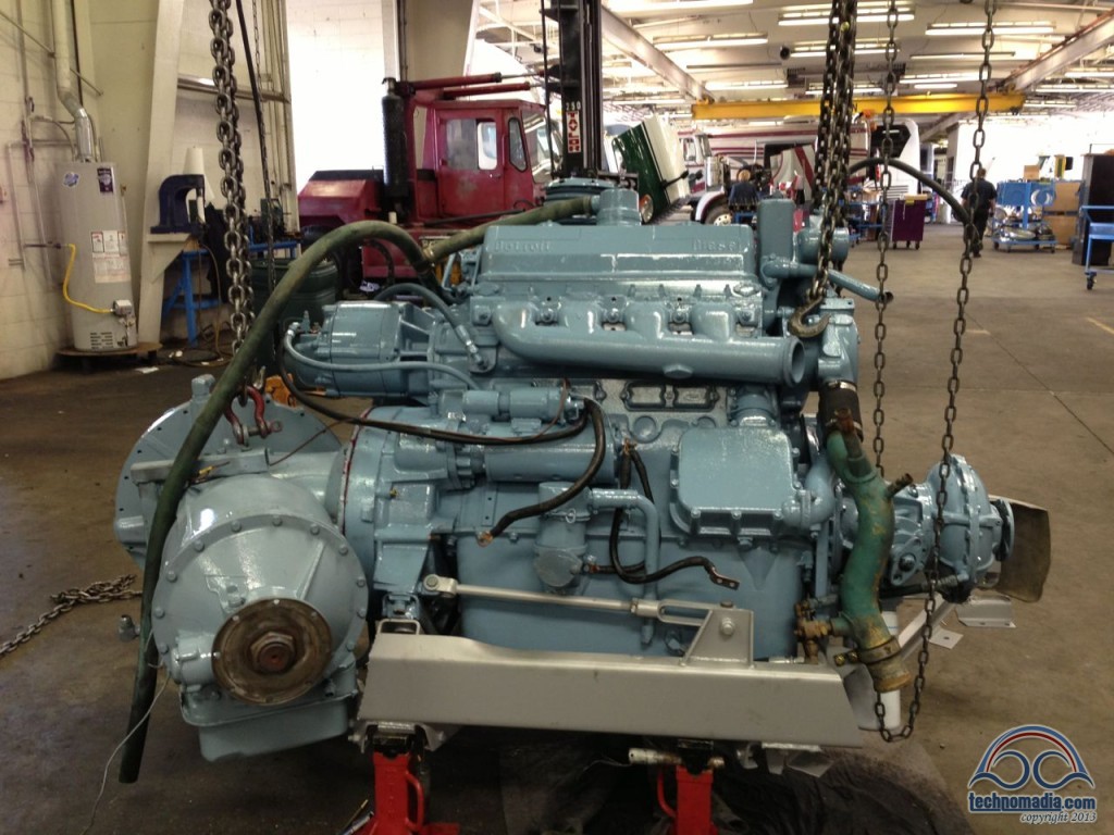
The Vernotherm valve is located in the bottom right of this rear shot. It has a temperature probe in the green pipe, which is the coolant return from the radiator. If the coolant is too hot, the Vernotherm restricts the oil flowing from the hose from the fan assembly back to the oil pan. The more restriction, the faster the fan spins.
A few weeks ago I would not have had the slightest idea what a Vernotherm was…
July 30th – The Engine Installed!
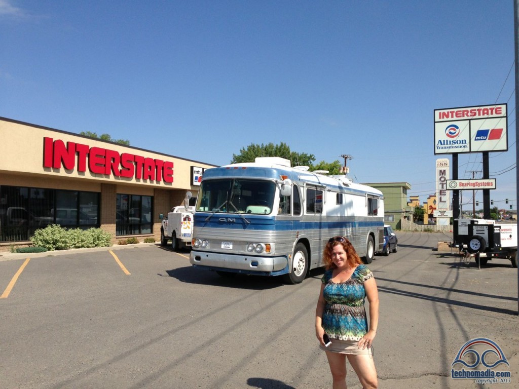
Finally, on the morning of July 30th, our bus was moved for the first time in 38 days as we were dragged by forklift into the service bay. It was time!
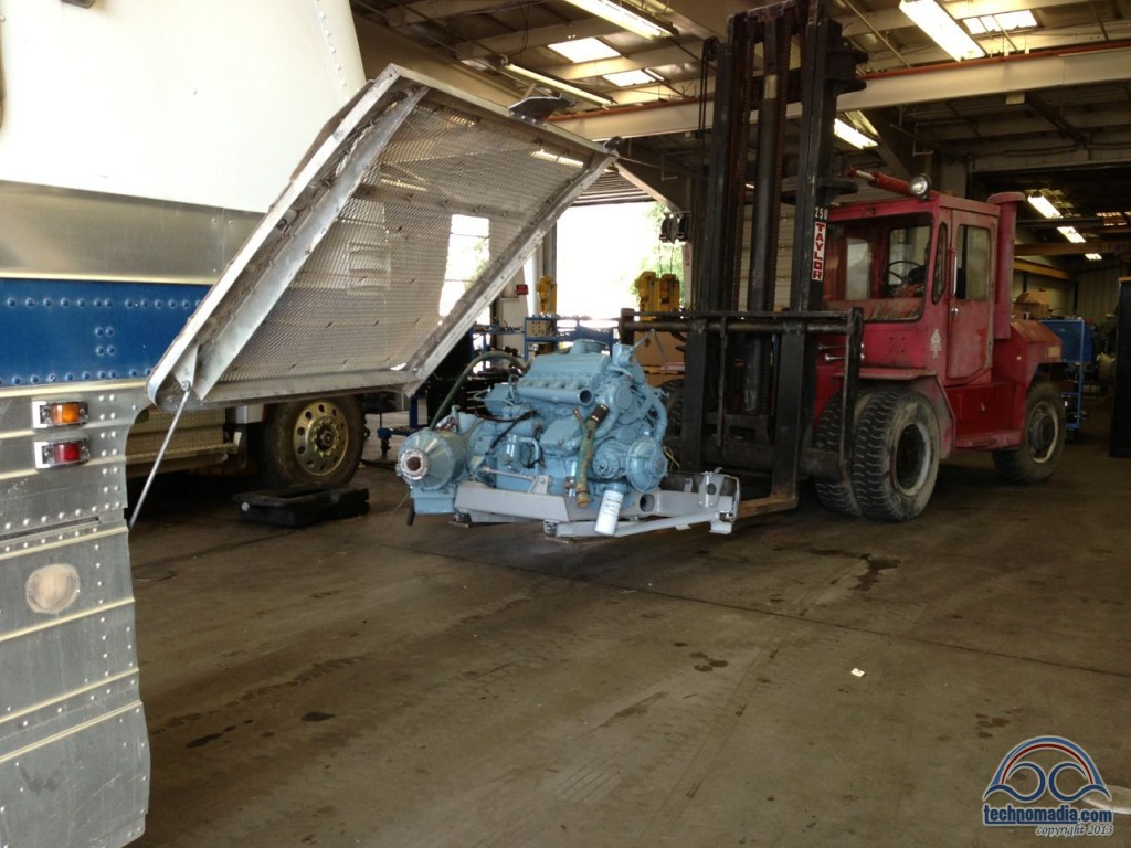
Actually attaching the engine and cradle to the bus is an amazingly simple affair (assuming you have a forklift that is) – it literally is only attached with four bolts. There are two at the back rear of the engine, and two hanging girders that support the weight from above.
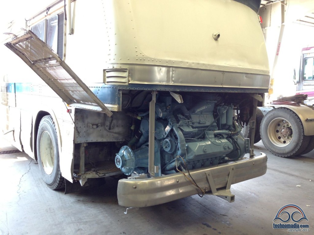
But hooking everything up once the engine is docked is still a big challenge – especially since we were adding a transmission cooler and a new bigger muffler to the mix. The shop’s goal was to get us on the road by the end of the month, but it was quickly becoming clear that we weren’t going to make it. At the end of the day things still seemed a long way off.
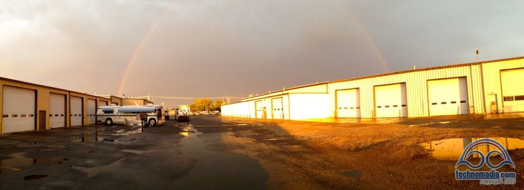
But, then, rainbows! A good omen!
July 31st – Unexpected Complexity
The next day things that we had hoped would be simple proved to be much more complex.
In particular, while we knew that the particular 5″ outlet muffler that we were upgrading to could theoretically fit into a 4106 (as done so by our bus-nut friend Mark), when it came time to make it happen it became clear just how tight things would be.
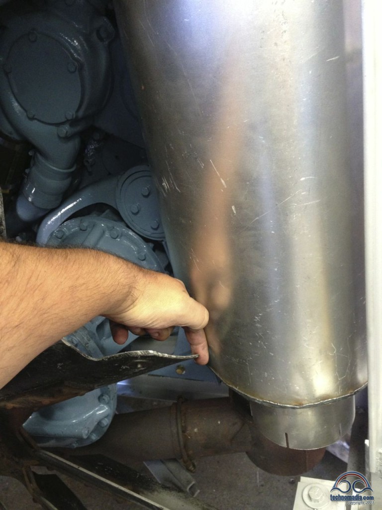
It required some extensive custom fabrication to get things to fit in a way that would all line up.
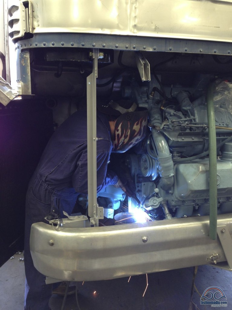
The final piece, crafted by fabrication master Jerry:
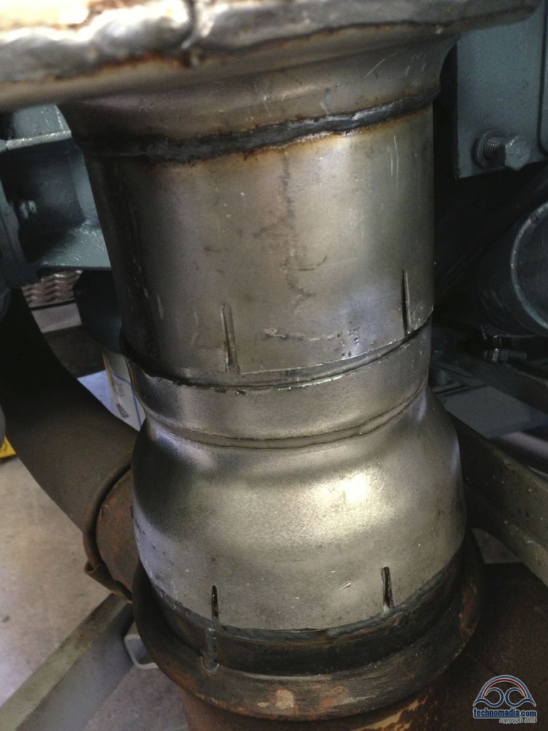
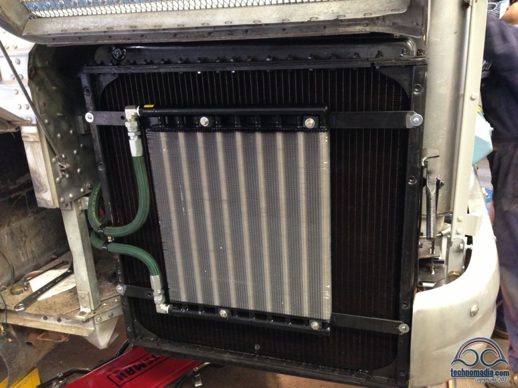
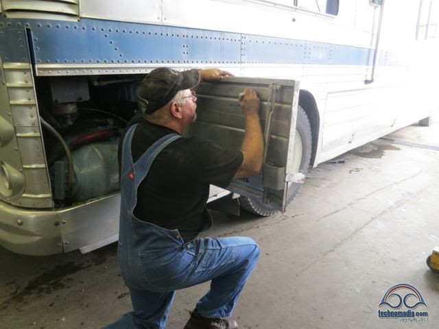
The new transmission oil cooler also proved to be a bit tricky – requiring us the change how we were initially mounting it so that it could fit without interfering with the existing grill door that protects the radiator.
We also had to figure out how to run the hoses across the back of the engine. In the process, we decided to change how the existing transmission cooler was plumbed – restoring the ability to swing out our radiator for service. (This is especially handy since the new taller muffler makes access to the area behind very difficult otherwise now…)
The month ended, and our bus was still needing to be towed in and out of the shop each day by forklift…
Thursday, August 1st – August Begins With a Vroom!
The next day we at last wrapped up the plumbing for the transmission cooler, and were able to at last fill up the fluids. The shop impressed us by going back over everything in the engine with an extreme attention to detail – securing hoses and wires in a fashion better than it had ever been before.
They even used touch-up paint to polish up the scuffs from installing the engine.
Then it was time for the first start! Vroom!!!
Everything seemed great, but as we were testing everything we noticed that the fuel pressure getting to the engine was lower than it should be when under high RPM’s.
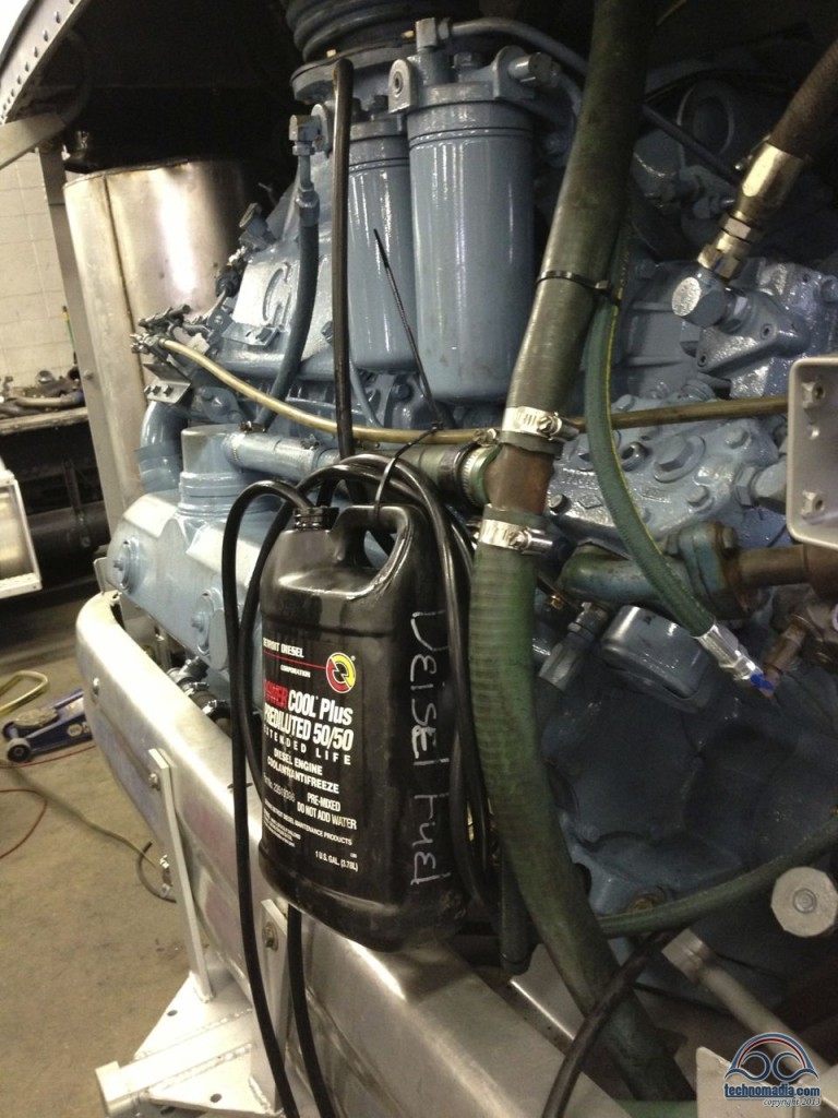
Troubleshooting involved replacing the fuel check-valve, blowing air through the lines, and then trying to isolate just where the blockage might be. The worst case scenario was that we’d run a new fuel line in the morning. Then – attach the rear door, lube the throttle cable, and we should be good to go!
And – at least we were able to pull out under our own power, though using a bit of a redneck fuel tank strapped to the back of the engine…
Friday, August 2nd – The Roller Coaster
The next day, Friday August 2nd, was exceedingly frustrating – and turned into an emotional roller coaster.
The simple lubing of the sticking throttle cable for a while seemed to be morphing into “your throttle cable is shot,” as each attempt to lube it actually made it worse. And the attempts to isolate the fuel line issue (which was probably there all along) felt like they were going in circles.
And then – during one test start – I saw sparks shooting out from behind the engine!!!
For a while we all actually thought the starter had fried – the hardest thing on the engine to get at while the engine is installed!
The hope of getting out of Billings in time for Cherie’s birthday was dwindling rapidly.
It wasn’t until late in the day that our fortunes seemed to turn. The starter turned out to be fine, the cable from the starter to the alternator hadn’t been wrapped well enough and had shorted. That turned into a simple fix.
And the magician of a mechanic Jamie crawled under the bus and managed to unstick the throttle cable, getting it moving smoother than ever.
And when it finally came time to give in and run another fuel line from the engine to the tank, though it did involve dumping out the contents of both of our cargo bays all over the shop floor – the actual work was quick and relatively painless!
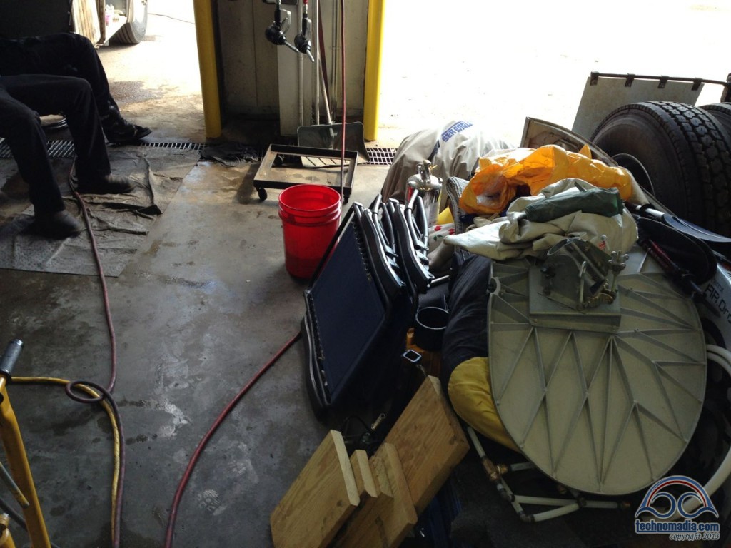
The shop had all hands on deck working on our bus that afternoon – things seemed to be coming together rapidly at last, and everyone was working late to handle all the little details.
Theoretically all that remained for Saturday morning were a few final tweaks, calibrating our new gauges (a story for another post!), and reattaching the rear door.
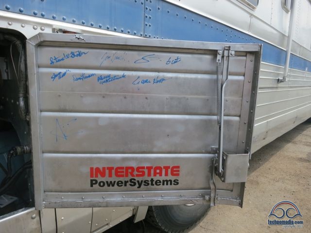
We were almost home free! We even started asking all the techs who had worked on our bus to sign their work – they are artists after all!
With a working fuel system, I asked if I could do a few test laps around the parking lot rather than just driving forward 35 feet out of the garage. I was itching to actually see the bus move a bit.
I got the go ahead, and the bus drove great!
Everything was going fine… Until I put it in reverse to back into our spot in front of our service bay.
And in the process painted the parking lot with a big stripe of transmission fluid.
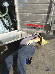
Uhoh.
We quickly discovered that the transmission reverse pressure sensor (unused in our bus, but normally used for backup lights or a beeper) must have gotten bumped and cracked during one of the trips on the forklift.
It seemed like a simple fix – just pull out the sensor, and plug the hole. But…
The sensor is in a tight spot right up against the engine cradle. It is a steel sensor corroded into an aluminum transmission body. And the extractor tool actually broke off while trying to remove it.
To fix it right might require dropping the transmission oil pan and valve body, which can’t then be reassembled without a special rare V730 gasket. One of which could not be found in Montana on a Friday night. Likely none would be available until Tuesday, at best…
The day ended in a funk instead of a celebration. Our service manager Scot invited us over for some much needed Vodka…
Saturday, August 3rd – A New Hope!
Saturday morning a full crew came in to help try to get us on the road. And miraculously, a fresh start and fresh eyes made short work of extracting the busted transmission sensor – without needing to perform major surgery.
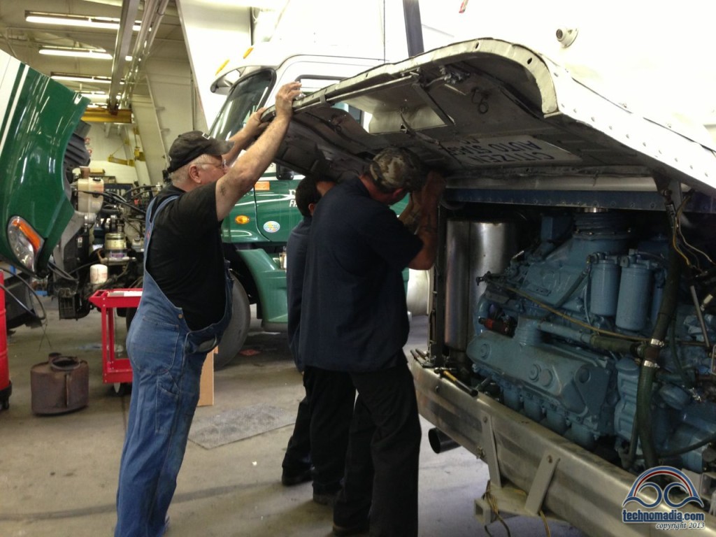
 Before lunch we had it removed and the hole plugged, the rear engine hatch on, and the battery bay cleaned up of the boiling acid, and the regulator adjusted to prevent this. (The newly rebuilt alternator was putting out too much power!)
It was time for a full-on road test – and Zephyr performed awesomely!!
We ended the afternoon with the final critical “Cold Beer Test” on my checklist, and then joined up with our service manager Scot and his wife Jodie to enjoy Johnny Winter opening up the Magic City Blues Festival.
Sunday, August 4th – Birthday On The Road!
We didn’t leave Billings until Sunday morning, Cherie’s 40th birthday. But we were there an extra night by choice, and not feeling trapped made all the difference in the world.
Thank you to everyone at Interstate PowerSystems who went above and beyond to take care of Zephyr, and us. We feel like we have made some great friendships along this journey.
Thank you Scot, Steve, Jamie, Larry, Anthony, Jerry, Marvin, and all the rest. You were an incredible team, and have a lot to be proud of.
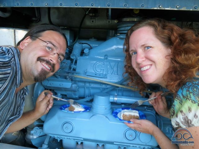
That evening – we camped alongside a beautiful mountain river, and ate birthday cake off of our newly rebuilt engine. We made it out of Billings for Cherie’s birthday after all!
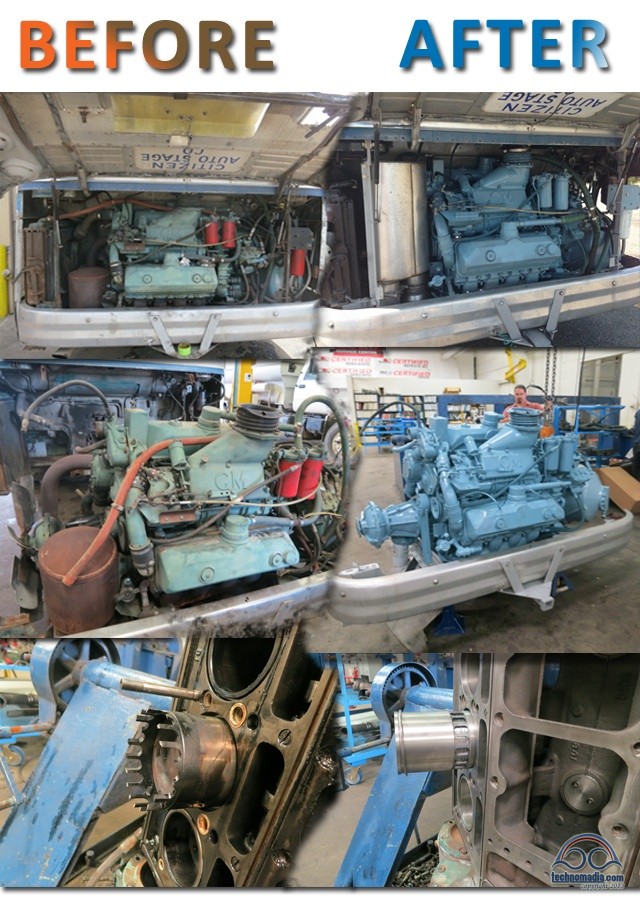
Before & After
It was a long (and expensive!) journey, but we always knew that someday we wanted to invest in making our home as awesome as she can be. The results are dramatic:
Related posts to our rebuild:
Decisions, Decisions, Decisions
To Repair, Replace, Rebuild or Repower our 8V71?
Disassembling and Dissecting a Detroit Diesel 8V71
Live Video Chat – TONIGHT!
Join us this evening for a live video chat where we’ll show off Zephyr’s newly overhauled engine, talk about the roller coaster ride of the 6-week rebuild process, and share about our performance results from her first 1000 miles of traversing mountainous terrain. As always, we’ll have an interactive Q&A session at the end.
Topic: Zephyr’s 8V71 Engine Rebuild
When: TONIGHT! (Tues, Aug 20)
Time: 6:30p PST / 9:30p ESTWhere: http://www.ustream.tv/
channel/technomadia RSVP here for reminders about this chat
View archives of our past video chats
Sign up to get e-mail notifications when we schedule future video chats

Hey! If you’ve got wheels connected to a 2 stroke GM you’ve got class!
First I would like to say I enjoy your story. All of it.
Secondly I would like to say we have joined your ranks with our recent purchase of a 1963 PD 4106. We have only used it twice so far. Once for 7 hours on the drive home, then the next weekend a 8 hour round trip to visit our friends in Spokane WA.
We are retiring next year and it is our plan to become Part Timers, not full timers. Living in the northwest makes it too difficult to be gone all the time.
Lastly, I do hope this does not offend you, especially since you have posted multiple places that having your brain picked is a terrible way to spend your time, but I do have a question that I can not find the answer to anywhere (believe me I have tried), and you have already dealt with it.
I am happy to Pay for the answers.
When you did your engine rebuild you replaced your existing muffler. The muffler on our bus is quite similar in looks to your original one, and VERY loud. I do want to get the noise level down without causing more back pressure to the 8v71. You mentioned Mark, your bus nut friend suggested a muffler, and after modifications you have it installed.
A short flurry of questions. 1) who makes it and what is it? 2) did it quiet down your bus? 3) did it cause you to lose any power? 4) did it cause your engine to run any hotter? Any help with this will be greatly appreciated and happily rewarded. Thank-you
Unfortunately, those aren’t questions we have good answers for. It’s been nearly 3 years since we did our engine rebuild, and don’t have the hand scratched notes available anymore 😉 Would recommend getting on the bus boards and asking around to see if others might have leads on mufflers that might fit.
Your other questions, would have required doing before/after comparisons with everything else being constant – which we did not do. Wasn’t like we were planning to do this. We had a total engine overhaul after a catastrophic failure, so trying to determine if the muffler had any of these impacts is near impossible.
Thanks for the fascinating story of the engine rebuild. Sounds like you had a crew that really puts their hearts as well as their hands in their work. Took me back to my days of working for the Santa Fe (1969-70) when part of my work involved going into the San Bernardino locomotive shop, where they would rebuild the “big brothers” to your 8V-71. The most common type was the V16-567, yes, that’s 567 cubic inches per cylinder. The railway museum I belong to has a retired Santa Fe passenger locomotive with a turbocharged V20-645.
And the name for your “Jimmy”, Zephyr recalls the early streamliner trains on the Burlington Route.
I’ve been wrestling with the trailer vs, Class A vs. Class C vs. bus/RV conversion for full timing for a while. Just when I’d narrowed it down to a GM 4104/06 type bus I read your horror stories! Now it’s back to the drawing board. Maybe a 5th wheel trailer + truck would be a more economical solution. You can get a whole used diesel dually plus a lifetime supply of tires for the cost of a major bus repair! Decisions, decisions!
There’s really no horror story here that you’d be able to absolutely avoid with any other choice. At the same time our bus needed an engine rebuild, we had 5 other RVing friends have MAJOR mechanical issues in a variety of RV types. They can all break down and need major stuff.
For us, it’s not about the most economical. For us, it’s about the most fun, the most quality of life. And we absolutely love our vintage bus conversion, it’s a classic and is more than just an RV to us. It’s got character, history and we love keeping a classic on the road. And heck, we only paid $8000 for it, far cheaper than we could have gotten almost any other setup. We just put away the cost of an engine rebuild upfront, so it wasn’t a big deal when the time came.
If a truck/5th Wheel combo is what works best for your lifestyle.. go for it.
They all have issues. Just like every home has issues. It’s not so much about large costs, it’s more about what suits your style and needs at the time.
How long did it take you to disassemble and reassemble the blower? Thanks
Oh gosh.. that was nearly 2 years ago, and the shop handled it. The details of each component are now a blur. 🙂 Check in on the various bus boards like http://www.busconversions.com and http://www.busnuts.com – they’re a great resources.
Great blog and awesome post!
Curious what the cost for your diesel engine overhaul was?
Steve
The cost was right in line with our expectations – we shared the various quotes we got for different approaches here: https://www.technomadia.com/2013/06/to-repair-replace-rebuild-or-repower-our-8v71/
Great post! Thanks for the effort that went into documenting the episode and writing the article.
Hey All – Glad you made it! There are sooooo many little details that will eat you up on a project like this and you just have to be patient and persevere which you both did well. Great write up. Well written for a wide audience of people. Hopefully we get to see Zepheyr…umm…I mean both of you at Arcadia!
-Sean
Good information. Well done.Will do it to ours 6V-71 down the road.
On the signatures, you might affix a piece of Lexan or 1/4″ plexi over it to preserve it!… Oil and such will eat it up…..
Dave5Cs
Great post! I now know what a “two stroke” diesel is now by looking at the pictures.
From a Dodge diesel fanatic!
Bill
Nice gesture to have all the mechanics sign their work.
Incredible job on the write up, almost as magical as the gifted techs that rebuilt your “baby”.
It brought back memories of my DD days, running the rack takes a special touch and it is a perishable skill, don’t think I could do it anymore. I had a pair of DD 2V71s that ran 60 KW generators on a Coast Guard cutter I was on in the late 80’s. One DD engine had over 12K hours on it and it ran like a top. Normal overhaul was at 4K hours, but this one ran so good, it was left in place.
Safe travels, you’re good to go for many more happy miles now. :c)
Good work, nice looking work. I like it when it feels like I’m making an investment rather than “spending money” and that’s what you were doing here. After “teething troubles” (which you’re going to have to expect even if you don’t run into anything), you should be good for *many* easy and dependable miles.
Congratulations on the great result.
Bruce H NC USA
Very cool post! Loved reading all the stuff you guys learned about your engine.
On that starter. Based on where it’s at how would you normally get to it if it needed replacing? Take apart your bedroom?
Glad you guys re-upped for the lighthouse. Can’t wait to start reading your posts about it. We’re jealous!
Hi Doc!
There are two general ways at getting at it. We do have an access panel in our closet that would make it slightly easier. And it is accessible without going through the bedroom by upping your yoga and contortionist skills. We’re practicing our flexibility, just in case! 😀
They put that in a crazy place! Seems like it would have been much easier on the other side, but that would mean regiggering the entire engine setup.
Thanks so much for detailing your rebuild adventure. I know that many folks will glean so much from it.
“Smiles to the Gallon” to ya!